Deep Dive: Tolerance Analysis in SolidWorks Using Design Tables
A time consuming and arduous process for mechanical engineers is analyzing a complex assembly of components to ensure that they can be assembled and function as intended within their defined tolerances. This process is typically referred to as a tolerance analysis, a tolerance assessment, or a tolerance stack-up. There are different methods that may be used to analyze a design, each more or less applicable, depending on the circumstances of the product, design risks, scale of production, and available resources.
While there is more emphasis on using Model-Based Definition (MBD) in design, we have found that traditional manufacturing partners continue to rely on hard-copy drawings. Model-Based Definition is a great goal and ultimately companies with more resources and vertical integration will continue to move in this direction. However, for small and medium sized businesses that might rely on a network to manufacture, the age-old process of creating 2D drawings from 3D models and analyzing them to determine acceptable dimensional tolerances continues to stand the test of time. The default process for a tolerance analysis in the non-MBD process is to leverage spreadsheets. A trusty friend of engineers, but at times overly relied upon. While these spreadsheets can be customized with Monte Carlo methods, various tolerance schemes, and company specific tweaks, using this method comes with drawbacks. Those include:
- A tedious process to analyze datums and tolerances that define the directions and stack-up.
- Difficult to capture a visual representation of the assembly within the spreadsheet.
- At times, it is insufficient at capturing stack-ups that occur in 3D space.
- Maintenance of the stack-up for a design change in the future is difficult and time consuming, especially if you were not the engineer who developed the stack-up initially.
- Requires manual entry of the determined tolerances from the spreadsheet to the drawing, increasing time and the potential for errors
The Approach & Benefit
Our approach can be summarized in a few basic concepts:
- Use tolerance definitions within the model to create worst case conditions
- Use Design Tables to leverage model tolerances to calculate dimensions of Worst-Case configurations
- Set up different Worst-Case components within an assembly to analyze tolerance stack-up
- Ensure critical dimensions within models are captured in engineering drawings
While this method does not provide a one-size-fits-all solution for analyzing assemblies, from our experience this method covers 80-90% of what is needed to perform a thorough analysis of an assembly. A few key benefits:
- It removes the process of creating a spreadsheet with separate images and dimensions that reflect the drawing. Separate documents lead to items being inaccurate, missed, and forgotten, where possible we prioritize a single source of truth.
- This process puts emphasis on defining the tolerance scheme early in the design process, before a drawing is created, minimizing the time required to iteratively update the model, drawing, and tolerance spreadsheet otherwise.
- Visual representation of fit is achieved in the assembly, allowing for intuitive adjustments and clearance measurements.
- Stack-ups that occur in 3-Dimensional space are visualized and analyzed as a part of the assembly, minimizing error and complex analysis in a spreadsheet.
- Future design changes all occur in the model and assembly and become more intuitive for the next engineer.
Process Explanation
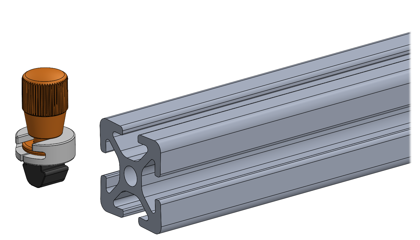
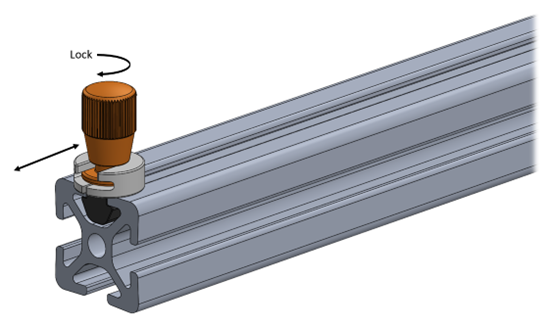
Let’s start by creating 3 parts that are intended to be assembled together. This sample assembly consists of a Screw, Washer, and Knob intended to slide along a rail, hold position on the rail when tightened, and always remain assembled when removed from the rail. To assemble, the Knob slides into the Washer t-slot and the Screw is threaded into the Knob through the bottom of the Washer. As the Knob is rotated, the Screw is pulled into the Washer and snaps into position, now retained by the Washer with limited travel.

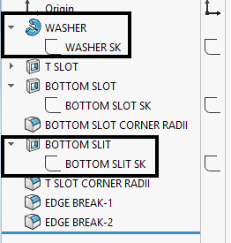
Before we dive into creating Design Tables, we recommend cleaning up the model in preparation. For easy identification and organization within the design table, we recommend first renaming features, sketches, and key dimensions before creating the design table. This makes information easy to identify as changes are made during the analysis. For dimensions and features that you already know will require tolerance control, go ahead and add in the desired tolerance within the sketch.
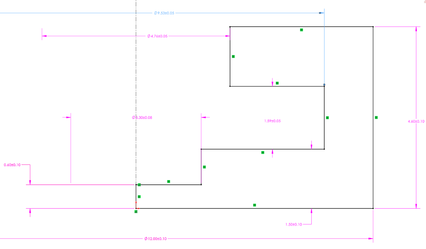
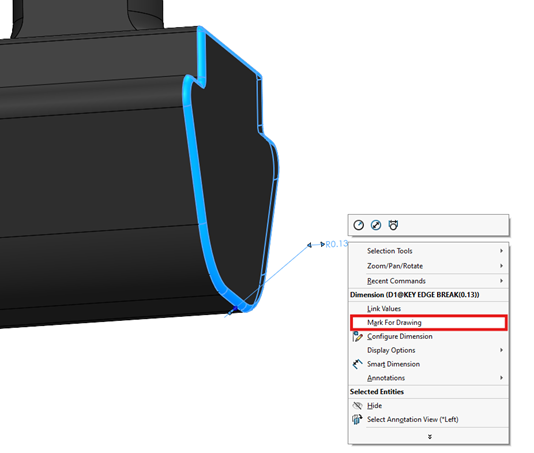
TIP : For any dimensions you do not want displayed on the drawing, such as reference dimensions or dimensions defined by drawing notes, right-click on the dimension and uncheck “Mark for Drawing”. This will prevent the dimension from being imported to the drawing. It is beneficial to do this now while determining your drawing dimensional scheme. Understanding what will or will not be defined in your drawing while finalizing your model is a useful exercise for thinking through what is critical for manufacturing.
We prefer to change the default configuration name to “NOMINAL”, but that isn’t required. Once the model is cleaned up, create a Design Table using Insert -> Table -> Excel Design Table. If you are not familiar with Design Tables, read our post about them. Once the table is created you can key in any dimensions needed into Row 2 of the table.
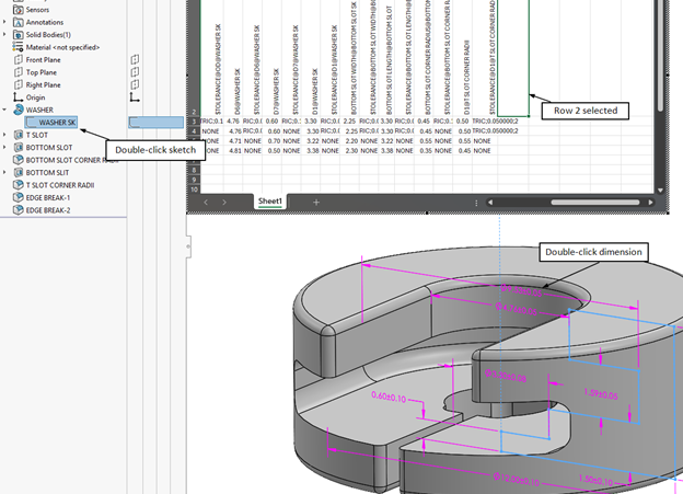
TIP : You can quickly add dimensions to the Design Table without typing each in. Open the sketch of interest by double-clicking on it in the feature tree, after dimensions are shown, you can double-click the dimension to have it populated into the design table. An important point here is that the cell selected in the design table needs to be Row 2 in order for this to work.
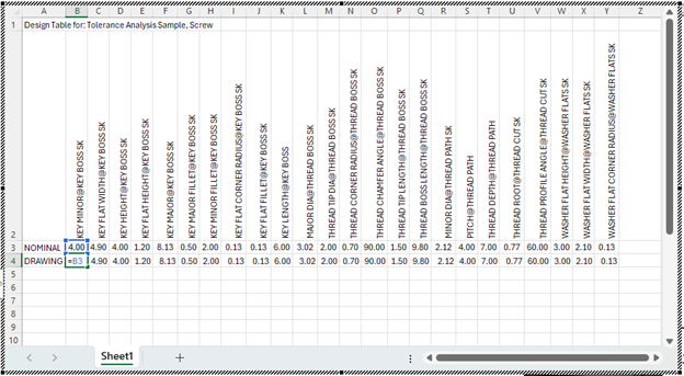
Create a new configuration named “DRAWING”. It is helpful to have this configuration as it will display the nominal dimensions and any tolerances which differ from the standard sheet tolerance in the drawing. We still want to analyze standard sheet tolerances in our Worst-Case models, but we don’t want them to show up in our final drawing, more on that later. Make all dimension values for the DRAWING configuration equal to the NOMINAL configuration.
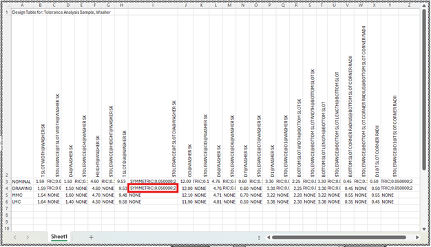
Add a column to the right of each dimension for that dimension’s tolerance. The heading should be “$TOLERANCE@” followed by the dimension name. For example, the tolerance heading for the Key Minor of the Screw component is “$TOLERANCE@KEY MINOR@KEY BOSS SK”.
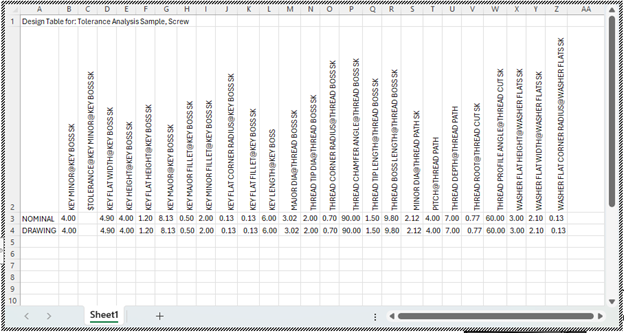
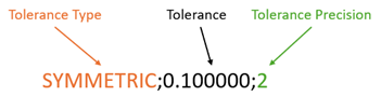
Add tolerance values to all dimensions, we recommend starting with a symmetric standard sheet tolerance for any that are yet to be determined. For a standard sheet tolerance of +/-0.10mm, the value should be “SYMMETRIC;0.100000;2”.
Listed in the table below are examples of tolerance values to input into the design table for each tolerance type.
| Tolerance Type | Example Specification | Tolerance Value for Design Table |
|---|---|---|
| Symmetric | 1.25 ± 0.25 | SYMMETRIC;0.250000;3 |
| Bilateral | 1.25 +0.15/-0.00 | BILATERAL;0.150000;-0.000000;3 |
| Max | 1.25 MAX | MAX |
| Min | 1.25 MIN | MIN |
For additional information about defining tolerance values in SolidWorks Design Tables see the SW Documentation.
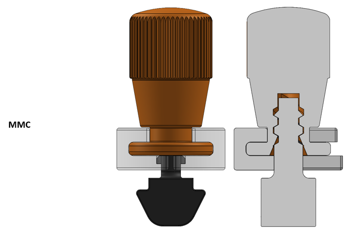
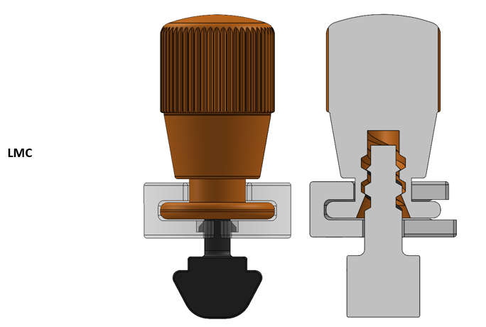
Create new configurations for worst case conditions MMC (Maximum Material Condition) and LMC (Least Material Condition). If additional worst-case configurations are known you might create those at this time as well.
The secret sauce of this method is leveraging Excel functions to access our defined tolerance values and calculate the final size for each configuration. The Excel MID function allows us to pull a chunk of characters from the middle of a text string. For example, if cell B2 contained the tolerance, “LIMIT;0.250000;0.150000;3", the Excel MID function would look like “=MID(B2,7,6)”, returning “0.2500”. The “7” in the MID function tells Excel how many characters to ignore starting from the left, and the “6” tells Excel how many characters to include in the extraction. Now that we understand how to use the MID function, we can use that to modify the dimension values in our worst-case configurations.
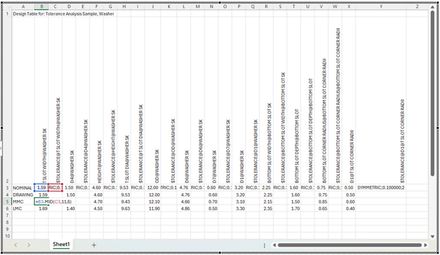
For MMC and LMC configurations add equations to the dimension values for each condition calculating the appropriate dimension based on the nominal value and tolerance value. In the example below, we are using the nominal value (B3) minus (-) the tolerance value (0.10) to calculate the dimension value for the MMC condition. So, in B5 the text entered is “=B3-MID(C5,11,5)”, which results in 1.49. Ensure you are carefully applying positive or negative modifiers to your features based on the worst-case condition. For an MMC hole the intent is to make it smaller and for an MMC boss the intent is to make it larger.
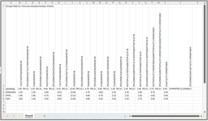
For the Worst-Case configurations leave the Tolerance field blank or add “NONE”. When exiting the Design Table, for any blank tolerance values, SolidWorks will automatically populate with “NONE”. When you exit the design table and rebuild, the MMC and LMC models will automatically update with the calculated dimension.
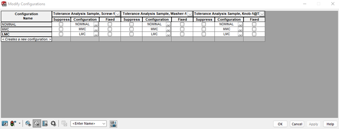
Navigate to the assembly model and create NOMINAL, MMC, LMC, and any other Worst-Case configurations needed to analyze the design. Configure each component so that the NOMINAL assembly configuration displays the NOMINAL components and so on for both the MMC, LMC, other configurations.
You can now switch between the configurations to analyze critical fits at the worst case conditions, checking for interferences (highlighted below) and visualizing maximum gaps. Within the Evaluate tab of the assembly file the “Interference Detection” and the “Clearance Verification” functions can be helpful in quickly determining where certain interferences or clearances exist.
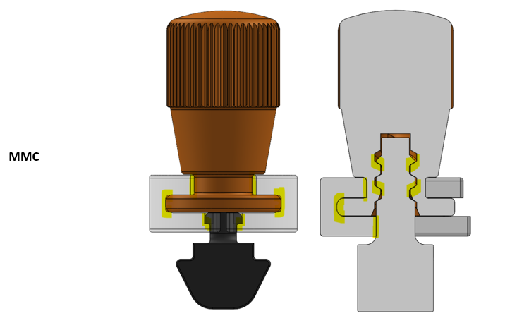
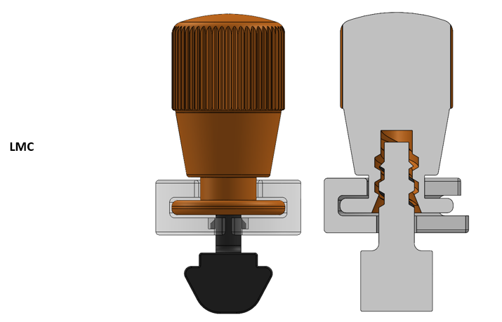
Now collisions and clearances can be easily visualized leading to a straightforward understanding to what needs to be adjusted to achieve the desired fit. Areas like threads that traditionally would be a tedious task to analyze if using a spreadsheet are now clearly visualized for the worst-case stack-up.
If a dimension or tolerance value needs to change, open the component design table and change the dimension value or tolerance value for the NOMINAL configuration. While not required, we recommend editing dimensions and tolerances within the Design Table. SolidWorks will prevent you from editing dimensions of a configuration if Excel is used to calculate the value. If working in the NOMINAL configuration, you will be able to adjust nominal values and tolerance values while editing features directly. However, if you try to edit values in MMC or LMC configurations, SolidWorks will prevent you from doing so. Additionally, it is best practice to open and save the Design Table after making edits in the NOMINAL configuration to ensure Excel functions update properly. You may also accomplish Excel updates by having each configuration rebuild upon Save or Rebuild.
Iteratively update component dimensions and tolerances to achieve the desired fit for the design.
Drawings
Once all dimensions and tolerances have been determined, check each component’s Design Table for any tolerances that differ from your standard sheet tolerance. For features that require tighter tolerance control make the tolerance value of the DRAWING configuration equal to the tolerance value of the NOMINAL configuration. Any tolerance value that matches the sheet tolerance of your drawing template should be left as “NONE” for the DRAWING configuration.
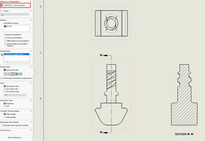
Import the model into the drawing and set up the appropriate views needed to define the model. Ensure that the DRAWING configuration of the model is selected for each view.
Using “Model Items” import the dimensions into the drawing for the model. While importing dimensions via “Model Items” can be a little messy to start, maintaining the link between the drawing and model is important to ensure dimensions and tolerances reflect 1-to-1. As changes are made in the model or the drawing, the link between the two will ensure that information in the model about a dimension, its tolerance, inspection criteria, notes, etc. is updated in the drawing. An important reminder here is that dimensions will be shown in the plane in which they are defined. So if a sketch exists on the Front Plane then that is the view “Model Items” will default to importing it into.
Take time to adjust the location of dimensions and move them between views using Shift+Select and dragging the dimension to a different view. After just a few minutes of manipulating the dimensions on the drawing, there are still a few problems that SolidWorks refuses to easily resolve. This is due to how the sketch is defined in the model. To add, there are a few leaders crossing that are generally messy and not desired.
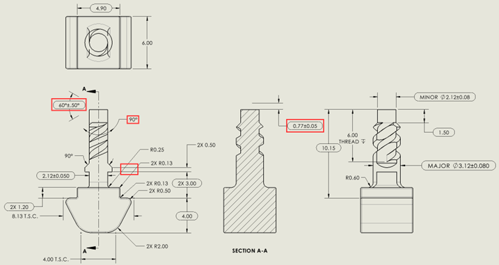
To resolve these issues there are a few options:
- For any dimension not critical to form or function, delete it and add it back into a more appropriate position or view using “Smart Dimension”. When doing this, make sure to add back in any additional notation or callouts (“2X”, “TYP.”, “T.S.C”, etc.).
- For any critical dimension (like the 60° and 0.77 defining the thread profile), you have two options:
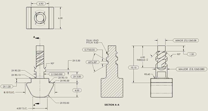
- In the model create a reference sketch that has the same definition as your dangling dimensions. It would be good practice to update your Design Table to ensure the reference sketch doesn’t get out of sync with your defining sketch.
- Alternatively, delete the dangling dimensions and use “Smart Dimension” to manually add in the dimensions and tolerance scheme. While more prone to errors and inaccuracies this method is easy and quick and sometimes that is what you need.
We typically default to creating a reference sketch unless there is good reason not to. Here is the cleaned up drawing.
Summary
Tolerance analysis is often treated as a downstream task — something done after the model is built, in a separate document, by a separate process. This method challenges that assumption by making the model the analysis. The result is a workflow that is faster to execute, easier to maintain, and more intuitive to interpret. It won’t replace every method in every situation, but for the vast majority of assembly fit and function checks, it is a practical and powerful alternative to the traditional spreadsheet approach.
If your team is working through a complex assembly and needs support with tolerance analysis or design validation, we’d be glad to help. Reach out to discuss your project.